Hardware
Laser Alarm System
Project Overview
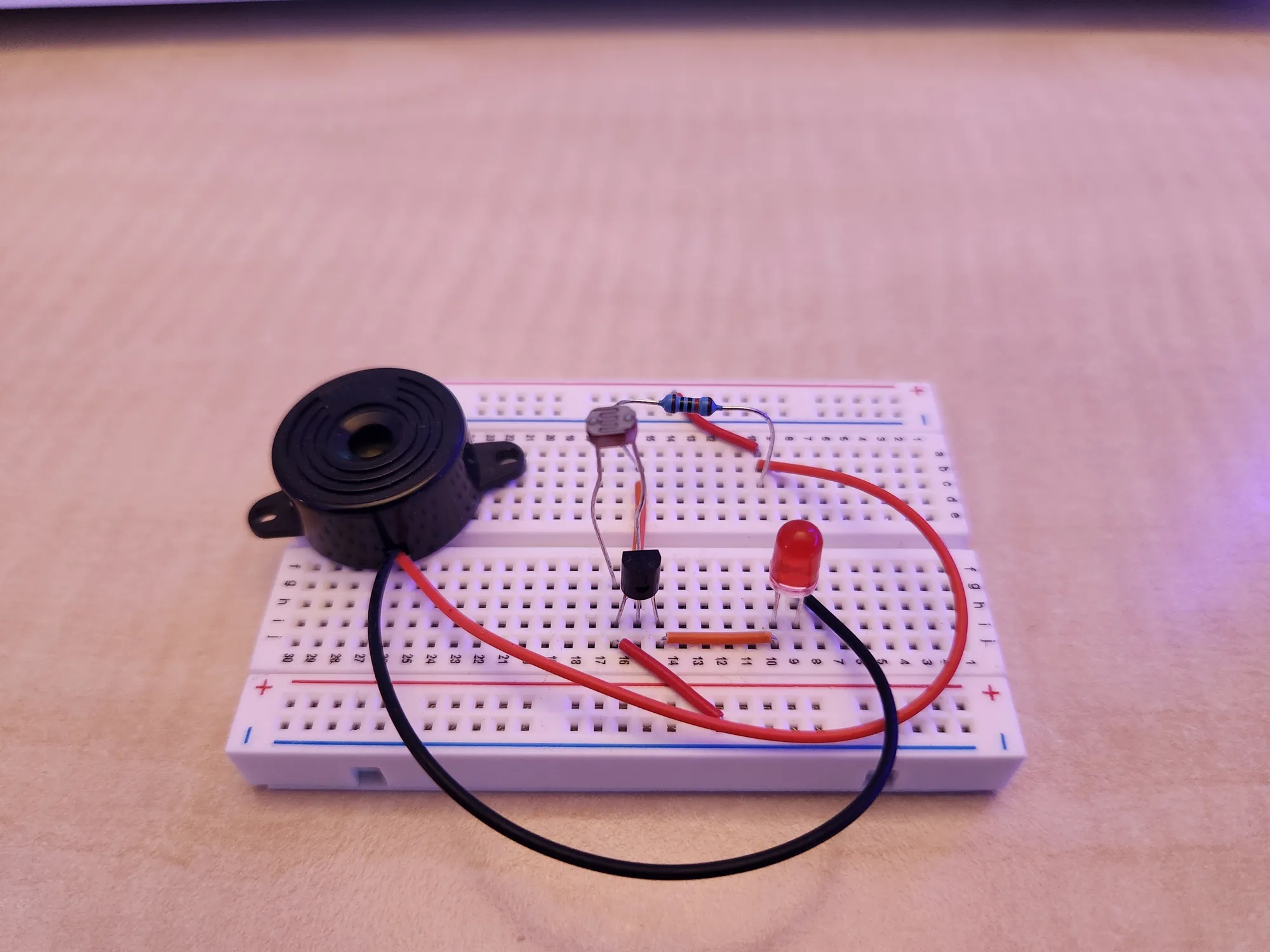
This project involves the design and construction of a breadboard-based security system that utilizes a laser and a light-sensitive sensor (LDR) to detect intruders. The system is designed to trigger audible and visual alarms when the laser beam is broken, mimicking industrial intruder detection systems.
System Specifications
This system functions as a simple electronic control circuit that monitors the light sensor's data and activates the visual and audible alarm outputs when the laser beam is broken.
System Logic and Operation
Logic
Circuit Details (Transistor Logic)
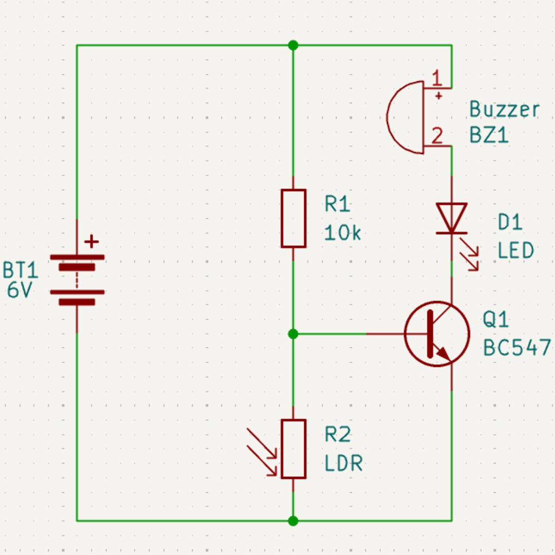
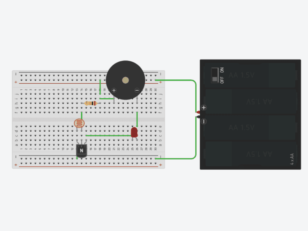
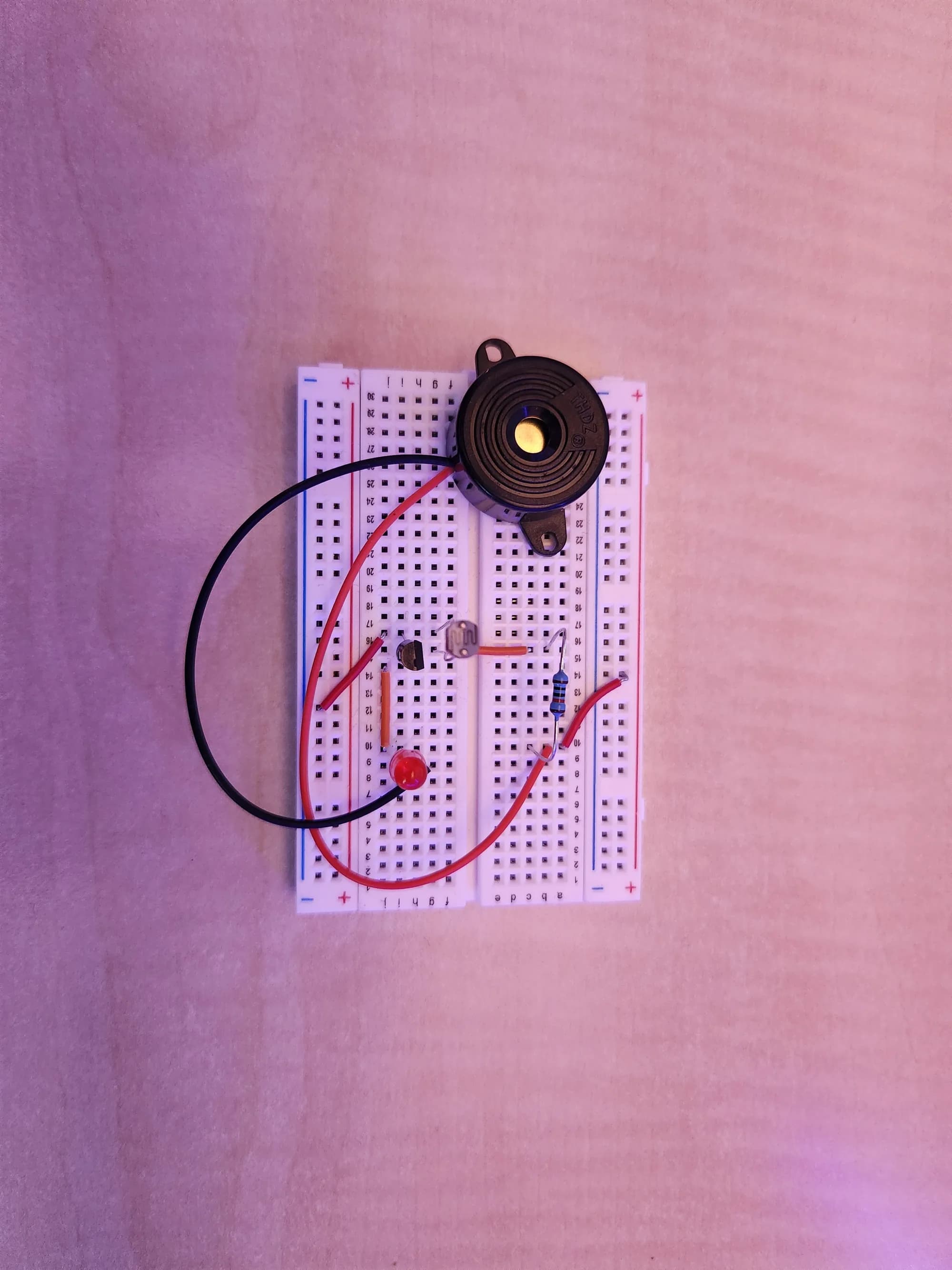
The circuit uses a voltage divider, consisting of the LDR and a resistor, connected to the base of a BC547 transistor. A buzzer and a red LED are connected in series to the transistor's collector, serving as the alarm outputs.
Operation
Armed State (Laser Intact): The laser beam continuously hits the LDR. The LDR's low resistance keeps the voltage at the transistor's base low. The BC547 remains OFF, keeping the buzzer and LED silent/dark.
Alarm State (Beam Broken): When the laser beam is broken, the LDR's resistance increases sharply, raising the voltage at the BC547's base. This turns the transistor ON, supplying current to the collector circuit, which activates the buzzer and illuminates the red LED.
Scope and Limitations
This laser alarm system is a prototype designed for indoor, short-range use only. Key limitations include sensitivity to ambient light, a non-latching alarm (it stops immediately when the beam is re-established), and reliance on battery power for operation.
Testing and Maintenance
Formal maintenance is minimal due to the prototype's simplicity. However, the system's operational integrity can be verified with a simple test procedure, outlined below.
Apply Power: Connect the battery. The system should remain in the Armed State (buzzer silent, LED dark).
Trigger Alarm: Obstruct the laser beam pointing at the LDR. The Red LED must illuminate and the buzzer must sound.
Reset State: Remove the obstruction. The system must immediately return to the Armed State (silent/dark).
| Date | Adjustment Made | Outcome |
|---|---|---|
| 10.04.2026 | Initial Assembly | Successfully tested on breadboard |